This guide explains how to configure a Site-to-Site High Availability (HA) redundant VPN tunnel between your Check Point SASE network and a Palo Alto Firewall, including both Firewall and Check Point SASE console configuration.
Pre-requisites
Before you begin, ensure that you have:
An active Check Point SASE account and a functioning network.
The Check Point SASE application installed on your devices.
An active Palo Alto Firewall account with administrative permissions.
Configuration in Palo Alto WebGUI
Step 1: Configure Tunnel Interfaces
Open the Palo Alto WebGUI and go to Network.
Select Interfaces and go to Tunnel.
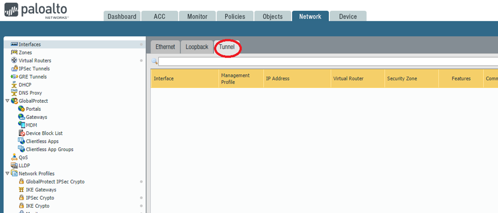
Click Add.
Configure these parameters:
Virtual Router: Select the virtual router for the tunnel interface.
Security Zone: Create a dedicated zone for tunnel traffic. If the tunnel interface is in a different zone than the source or destination, create a security policy to allow the traffic.
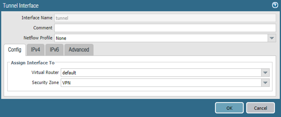
Click the IPv4 tab and click Add. Enter the internal address for the first tunnel (use the 169.254.x.x range).
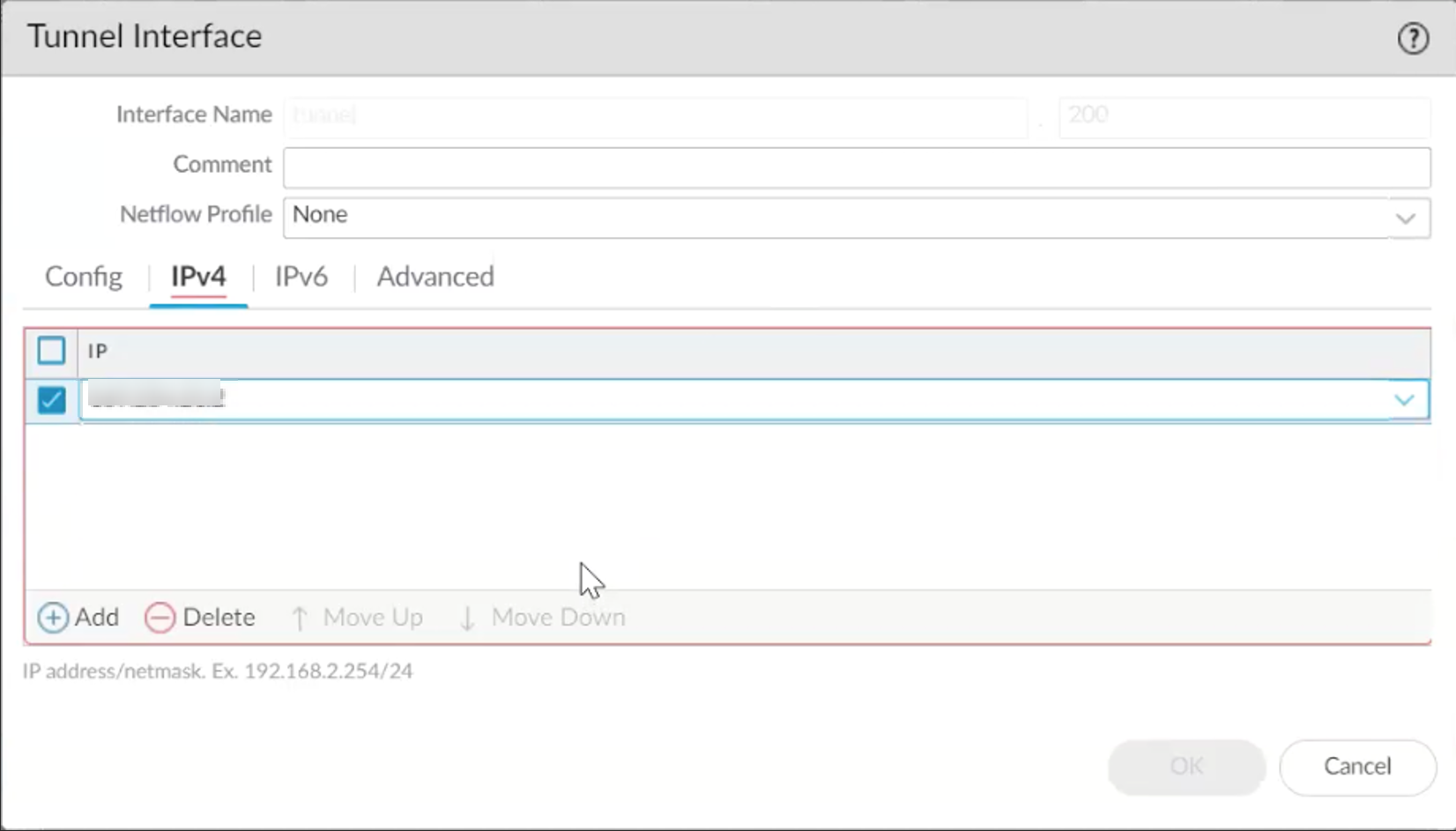
Click OK.
Repeat the steps to create the second tunnel interface.
Step 2: Configure IKE Crypto Profile
Go to Network Profiles > IKE Crypto.
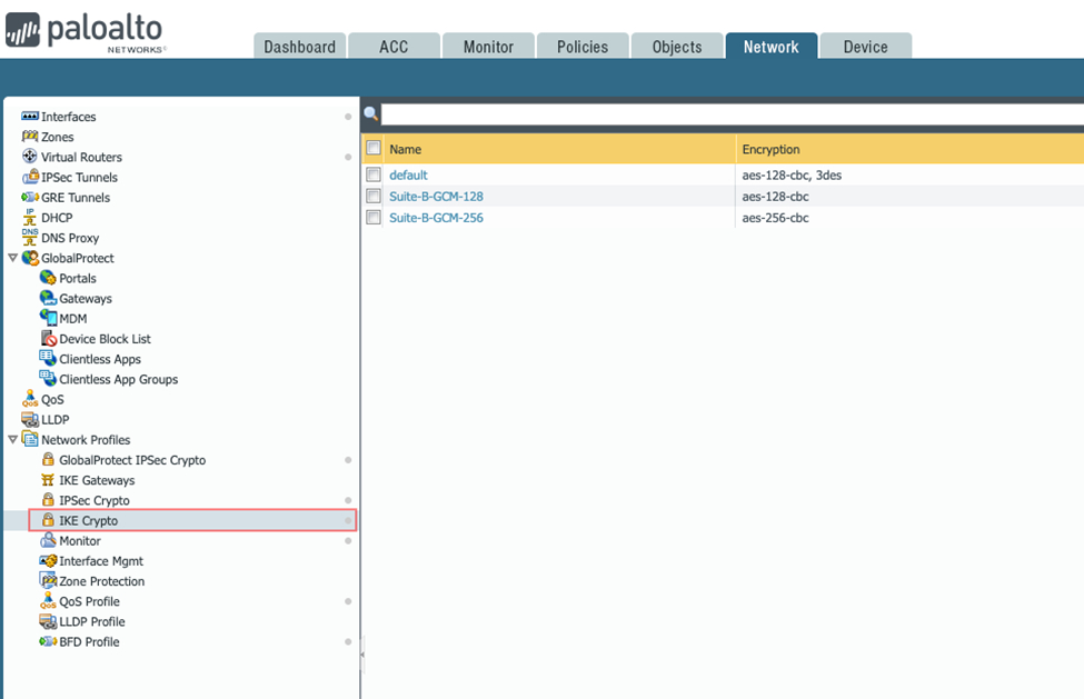
Click Add and define the IKE Crypto profile (IKEv1 Phase 1) parameters:
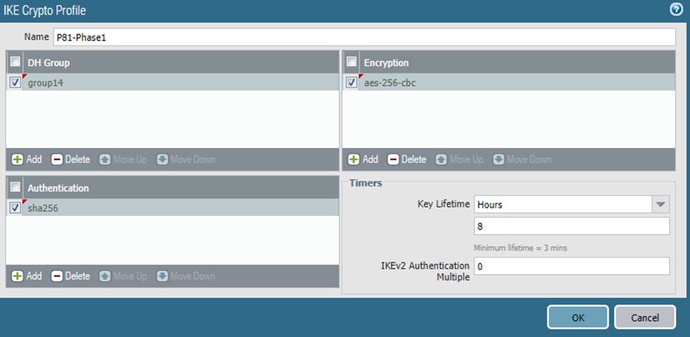
Name: Enter a descriptive name.
DH Group: 14
Encryption: aes-256-cbc
Authentication: sha256
Key Lifetime: 8 hours
IKEv2 Authentication Multiple: 0
Step 3: Configure IKE Gateway
Go to Network Profiles > IKE Gateway.
Click Add and fill these details:
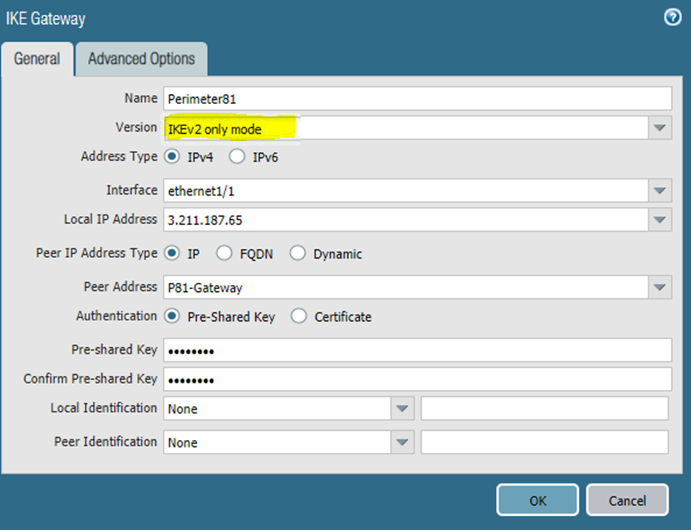
Name: Enter a descriptive name.
Version: Select IKEv2 (or IKEv1 if unsupported).
Address Type: IPv4
Interface: External interface connected to the internet
Local IP Address: External IP address
Peer IP Address Type: IP
Peer Address: Check Point SASE gateway IP
Authentication: Pre-Shared Key
Pre-Shared Key: Enter a strong key (mix of uppercase, lowercase, and numbers).
Note: Record this value for configuring the tunnel in the Check Point SASE management console.
Local Identification: None (Gateway uses the local IP as the local identification value)
Peer Identification: None (Gateway uses the peer IP as the peer identification value)
Repeat the steps for the second Check Point SASE gateway.
Step 4: Configure IPSec Crypto Profile
Go to Network Profiles > IPSec Crypto.
Click Add and enter these details:
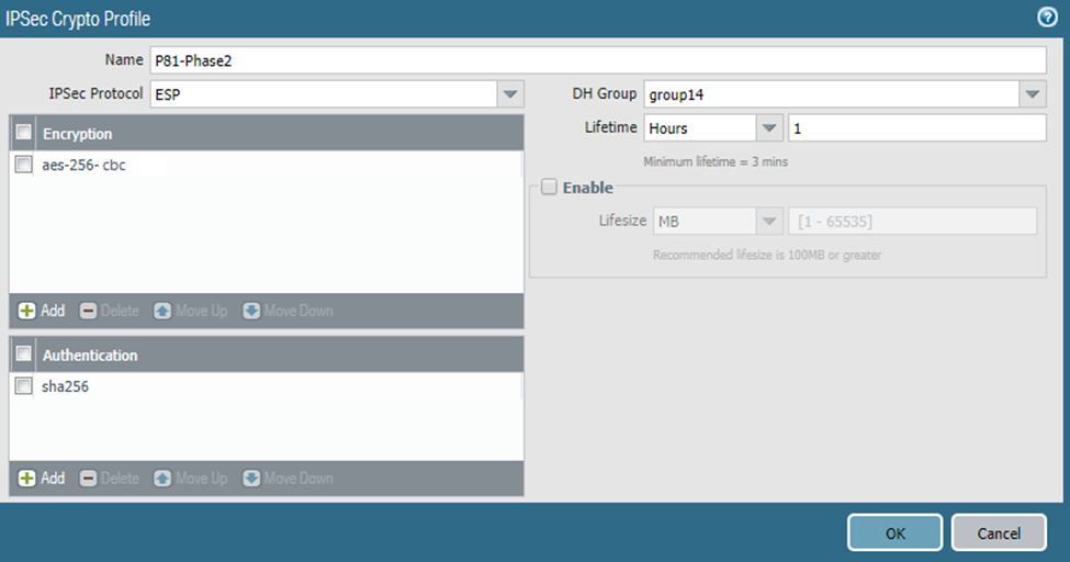
Name: P81-Phase2
IPSec Protocol: ESP
DH Group: 14
Encryption: aes-256-cbc
Lifetime: 1 hour
Authentication: sha256
Step 5: Configure IPSec Tunnels
Go to Network Profiles > IPSec Tunnels.
Click Add and enter these details:
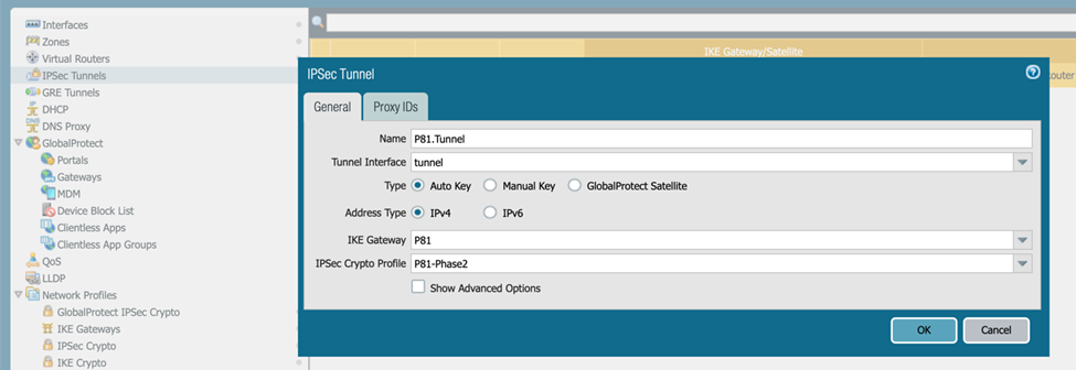
Name: Enter a descriptive name.
Tunnel Interface: Select the appropriate interface.
Type: Auto Key
Address Type: IPv4
IKE Gateway: Select the previously defined gateway.
IPSec Crypto Profile: Select the previously defined profile.
Repeat the steps for the second IPSec tunnel.
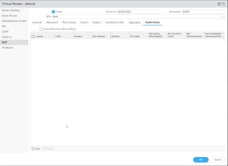
Step 6: Configure BGP
Go to Network Profile > Virtual Routers.
Click BGP and enter these details:
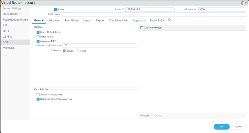
Router ID: Internal address for the first tunnel (from Step 1).
AS Number: AS number for the Palo Alto Firewall.
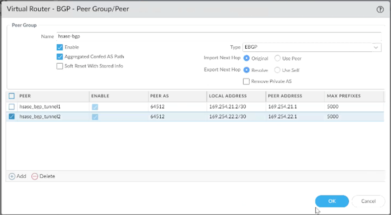
Add BGP Peer Group and Peers (for redundancy)
Under Peer Group, click Add and enter a name for the Peer Group.
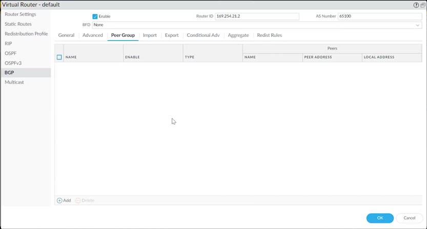
Under Peer, click Add.
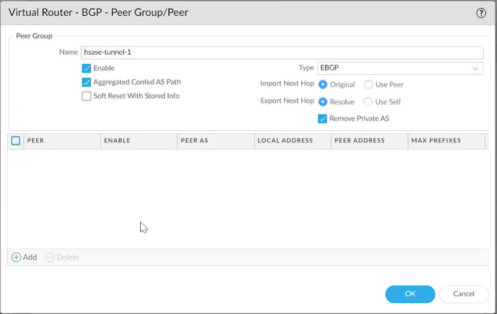
In the Peer window, configure these details:
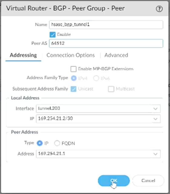
Name: Enter a descriptive name.
Peer AS: Check Point SASE AS number (default: 65000).
Local Address:
Interface: Select the first tunnel interface created in Step 1.
IP: Select the internal address assigned to the first tunnel.
Peer Address: Internal (BGP) address for the first Check Point SASE gateway.
Go to Connection Options, set Multi Hop to 3.
Repeat for the second tunnel interface.
The Peer Group configuration should resemble the example shown below.
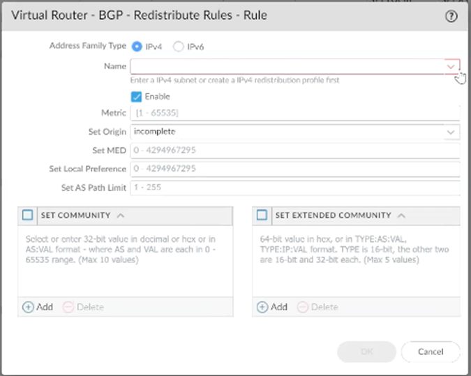
Step 7: Configure Redistribution Profile and BGP Import Rules
Redistribution Profile
Go to Virtual Router > Redistribution Profile > Add.
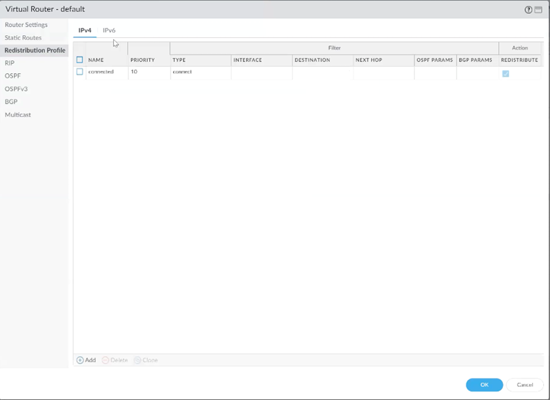
Configure:
Name and Priority
Enable Redist
Under General Filter, check Static
Click OK.
BGP Import Rules
Go to BGP → Import → Add.
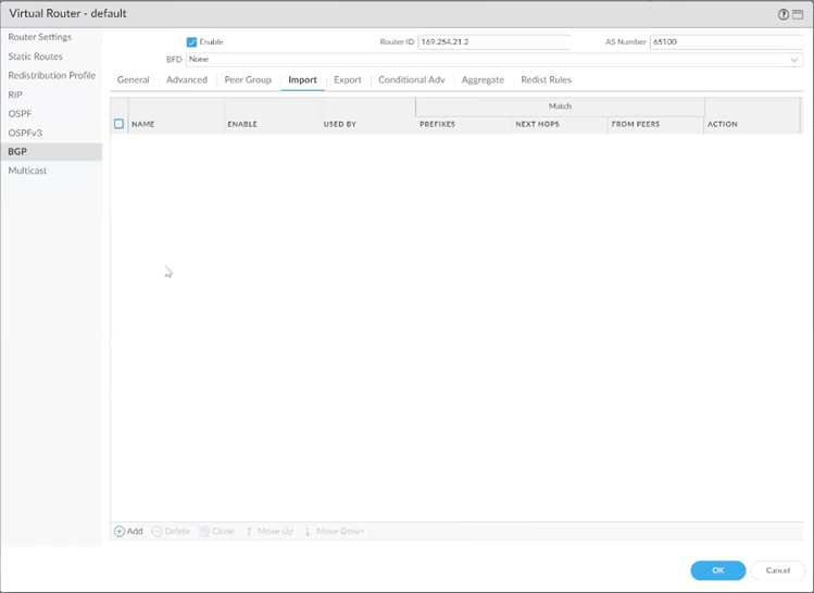
Enter a Name for the rule.
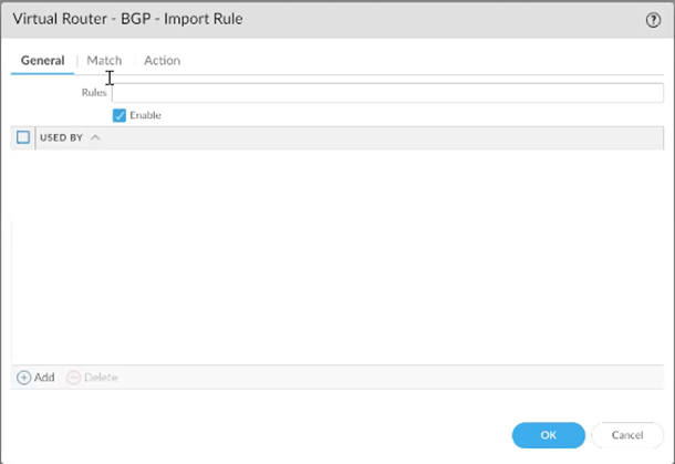
Click Add and select the created peer group.
Under Match, configure:
AS Path Regular Expression: _<SASE AS>$ (replace with the actual SASE AS)
FROM PEER: Select the two tunnel interfaces created previously.
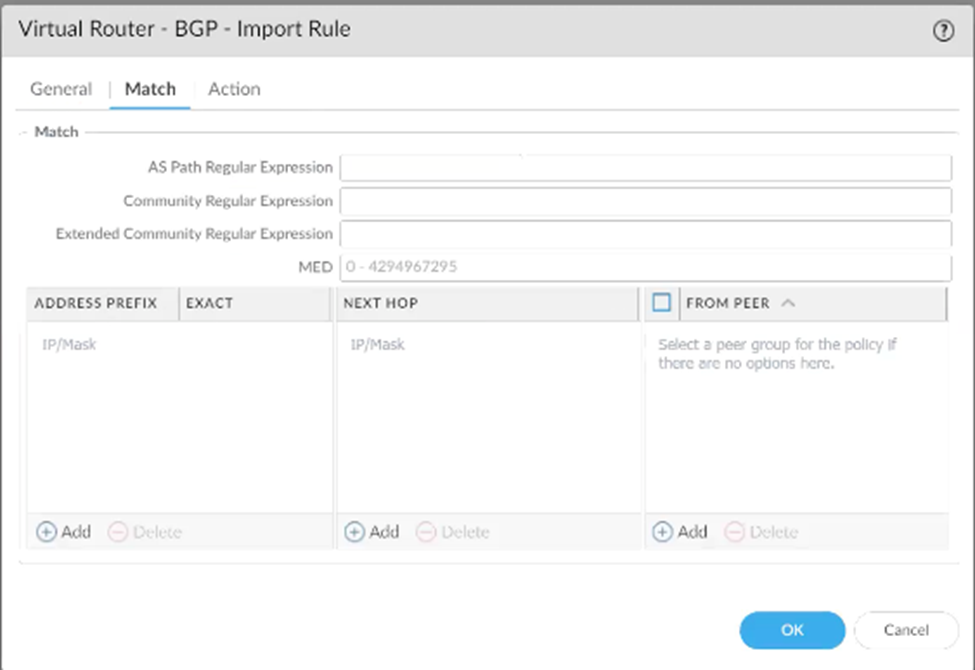
Under Action, choose Allow.
Under Redist Rules, click Add and select the redistribution profile created earlier.
Click OK.
Step 8: Configure Security Policies
Open the Policies tab and select Security.
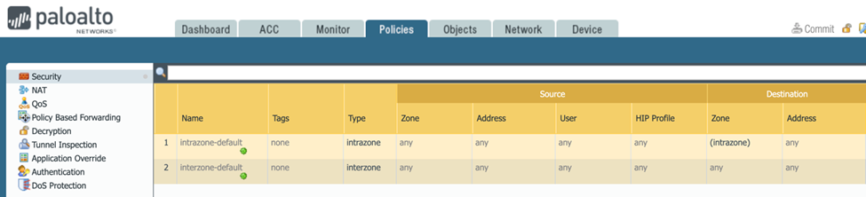
By default, IKE negotiation and IPSec/ESP packets are permitted.
If behavior differs or if you require more granular traffic control, click Add and create an appropriate Security policy rule.
Click Commit to apply the configuration changes.
Configuring the tunnel in the Management Platform
Step 1 : Configuring Tunnel and Routes Table
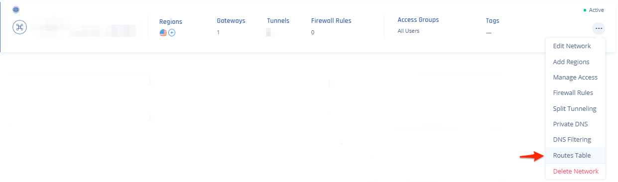
Access the Check Point SASE Administrator Portal and click Networks.
.png)
Select the network.
Click
 .
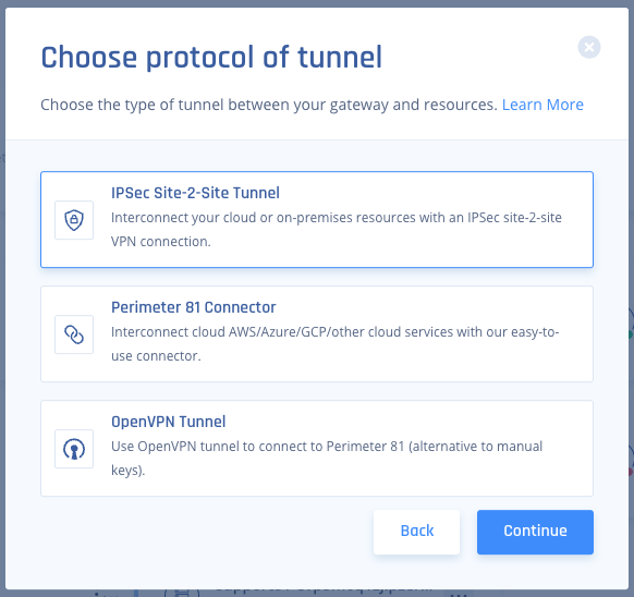
.Select Add Tunnel for the gateway from which you want to add the IPSec Site-to-Site VPN tunnel.
Click IPSec Site-2-Site Tunnel and click Continue.
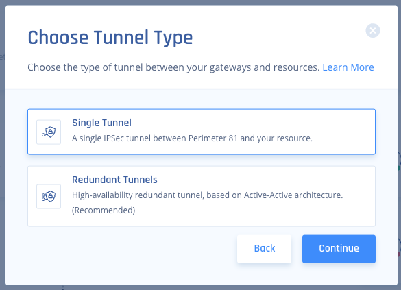
Click Redundant Tunnels and click Continue.
In the Tunnel name field, enter a logical name.
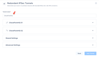
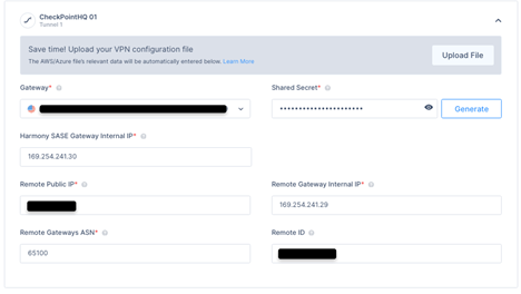
Expand Tunnel 1 and specify these:
Shared Secret – The value previously set on the first IKE Gateway.
Check Point SASE Gateway Internal IP - The SASE internal IP address as you configured in the first PEER Group.
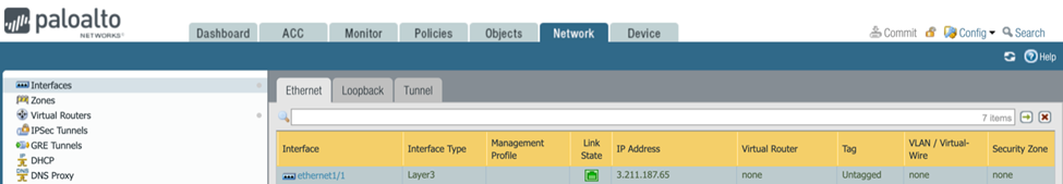
Remote Public IP - Enter the FW's external Interface IP. This can be found in Palo Alto WebGUI under Network /Interfaces /Ethernet.
Remote Gateway Internal IP - The FW internal IP address as you configured in the first PEER Group.
Remote Gateways ASN - The ASN of the Palo Alto Firewall.
Remote ID - Enter the same value as per Public IP. If behind NAT, enter the internal LAN IP of the Palo Alto Device (example 192.168.1.1).
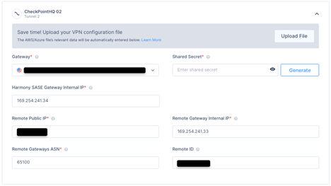
Expand Tunnel 2 and specify these:
Gateway - Select the second Check Point SASE Gateway for the tunnel.
Shared Secret - The value previously set on the second IKE Gateway.
Check Point SASE Gateway Internal IP - The SASE internal IP address as you configured in the second PEER Group.
Remote Public IP - Enter the FW's external Interface IP.
Remote Gateway Internal IP - The FW internal IP address as you configured in the second PEER Group.
Remote Gateways ASN - The ASN of the Palo Alto Firewall.
Remote ID - Enter the same value as you did Public IP. If behind NAT, enter the internal LAN IP of the Palo Alto Device (example 192.168.1.1).
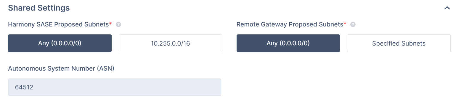
Expand Shared Settings and specify these:
Check Point SASE Gateway Proposal Subnets - Leave Any (0.0.0.0/0) selected.
Remote Gateway Proposal Subnets - Leave Any (0.0.0.0/0) selected.
Autonomous System Number (ASN) - Default value is 64512, if not set, enter the AS Number for the Check Point SASE network.
In the Advanced Settings section, specify these:
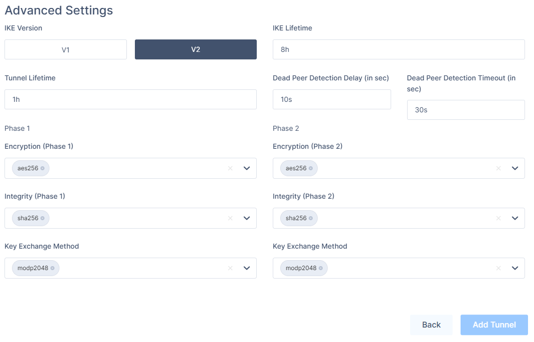
IKE Version: V2
IKE Lifetime: 8h
Tunnel Lifetime: 1h
Dead Peer Detection Delay: 10s
Dead Peer Detection Timeout: 30s
Phase 1:
Encryption(Phase 1): aes256
Integrity (Phase 1): sha256
Key Exchange Method: modp2048
Phase 2:
Encryption(Phase 2): aes256
Integrity (Phase 2): sha256
Key Exchange Method: modp2048
Click Add Tunnel.
Select Routes Table:
Click Add Route.
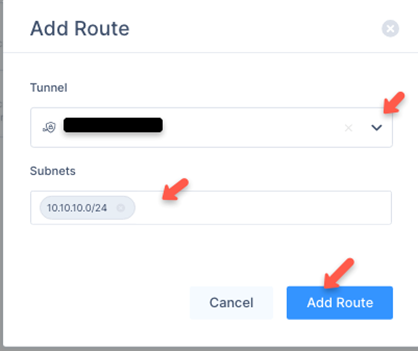
The Add Route window appears.
Enter all the subnets on the remote side of the tunnel and then click Add Route.
Note: Make sure that in the Tunnel list, you have selected the previously entered Tunnel name.
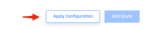
Click Apply Configuration.
Step 2: Verifying the Setup
Once you complete the above steps, the tunnel becomes active.
Verify the setup in the Check Point SASE Administrator Portal:
Click Networks.
Locate the tunnel you created, and check the tunnel status.
It should indicate that the tunnel is Up, signifying a successful connection.
Verify the setup in the Check Point SASE Agent:
Connect to your network using the Check Point SASE Agent.
Access one of the resources in your environment.
Troubleshooting
If you encounter issues during or after the setup, review your settings to ensure everything matches the instructions. Check the IP addresses and other details you entered during setup. If issues persist, please consult our dedicated support.
Support Contacts
If you have any difficulties or questions, contact Check Point SASE's support team. We offer 24/7 chat support on our website at sase.checkpoint.com, or you can email us at sase-support@checkpoint.com.