
This article describes the Check Point SASE IPSec Site-2-Site tunnel feature.
IPSec Tunneling is a security feature that allows you to create a secure communication link between two different networks located at different locations using the IKE VPN protocol. By creating an IPSec Tunnel, you can connect your Check Point SASE gateway to your local network or cloud services, for remote access.
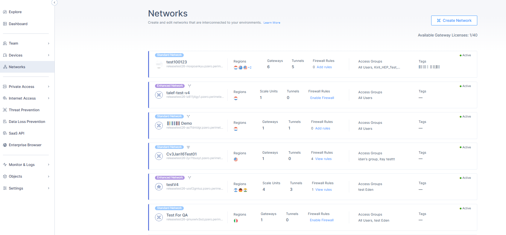
To create a tunnel, begin by navigating to the Networks screen, and clicking on the ellipsis next to the gateway ("...") -> Add Tunnel -> IPSec Site-2-Site Tunnel.
IPSec handshake
The IPSec tunnel employs a two-phase handshake. The handshake interval is determined by the tunnel's lifetime values.
Phase 1 (Also known as IKE or Gateway): This Security Association is in charge of the external IP communication between the Check Point SASE network and the remote IP using port 500/4500.
- Shared Secret
- Public IP
- Remote ID
- IKE Version
- IKE Lifetime
- Encryption (Phase 1)
- Integrity (Phase 1)
- Key Exchange Method
Phase 2 (Also known as ESP or Tunnel): This Security Association is in charge of internal LAN range or subnet handshake after IKE SA has already been established.
- Check Point SASE Gateway Proposal Subnets
- Remote Gateway Proposal Subnets
- Tunnel Lifetime
- Dead Peer Detection (DPD)
- Encryption (Phase 2)
- Integrity (Phase 2)
- Key Exchange Method
Policy-based vs. Route-based IPSec
This is an example of a Policy-based connection: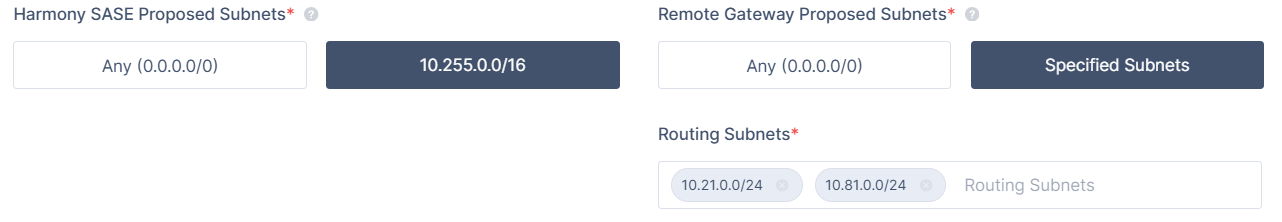
- This kind of connection is easier to set up but is more vulnerable to IPSec tunnel value mismatch.
- Depending on your router's vendor, a single subnet that's missing from the Policy-based IPSEC handshake may cause the entire Phase II negotiation to fail.
On the other hand, this is what a Route-based (also known as a Tunnel Interface or VTI) connection looks like:
- It is a more modern and stable method of IPSec tunneling.
- Once established, it uses one subnet (0.0.0.0/0) for the handshake, so there is less room for error upon renegotiation.
- After this, you must input the route for this tunnel.
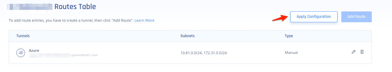
- To add a route, click the "..." button at the top right corner of the network -> then select Routes Table.
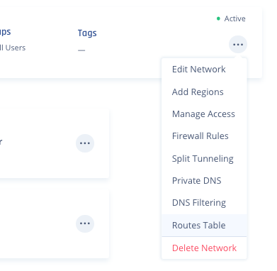
- Click on Add Route.
.png)
- Input all of the Subnets on the Remote Side of the tunnel, then click "Add Route"
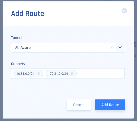
- After you are done, click Apply Configuration.
- To add a route, click the "..." button at the top right corner of the network -> then select Routes Table.
Single tunnel
A single tunnel serves as the minimum requirement option to create an IPsec tunnel into internal resources. A network can include one or more gateways, in case of multiple gateways, all tunnel traffic will be routed through this tunnel via a specific gateway.
Creating a single tunnel
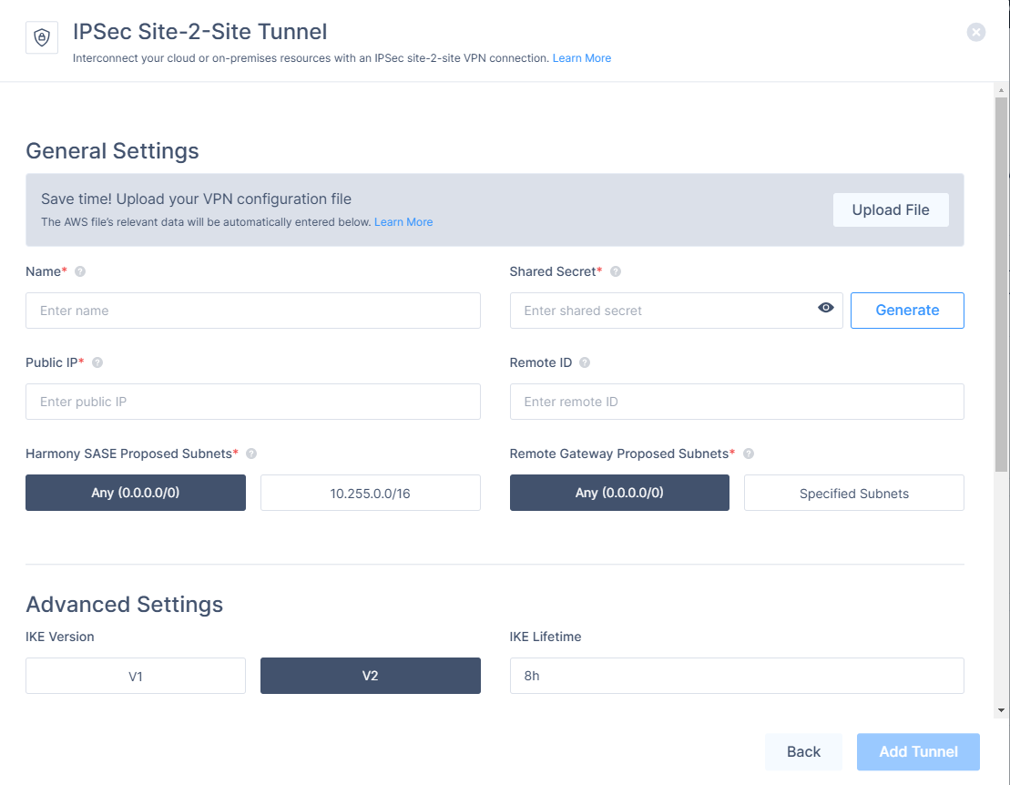
- Name: The name of the Tunnel you want to create.
- Shared Secret: A pre-shared key that will be used by both of the tunnel parties.
- Public IP: This is the public IP address of the second end of the tunnel,
- Remote ID: In most cases, the ID of the remote tunnel is the public IP of the tunnel. However, it must be configured to the same value on both ends.
- Check Point SASE Gateway Proposed Subnets: The IPSec network selector must be configured to the same value at both ends of the tunnel.
- Remote Gateway Proposed Subnets: The remote subnet selector must be configured to the same value on both tunnels ends. If you do not specify the subnets, you will need to do so manually using the Check Point SASE Routes Table configuration.
.PNG)
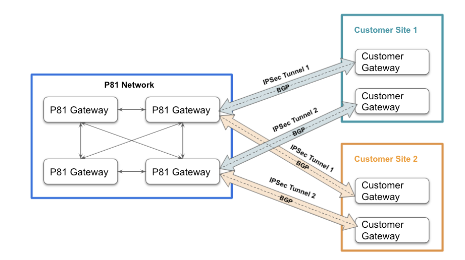
Redundant tunnels
The Redundant Tunnels feature is designed to improve high network availability for customers that use IPSec tunnels from Check Point SASE gateways to their cloud or on-premises resources.
This feature adds the ability to create two IPSec tunnels between two different Check Point SASE gateways and two different customer gateways. The feature utilized BGP and allows Active-Active architecture, achieving both redundancy and better performance by routing users to a tunnel that is closest to their location.
- To configure a redundant tunnel to AWS, see AWS Redundant Tunnels with AWS Virtual Gateway or AWS Transit Gateway for multiple AWS VPCs
- To configure a redundant tunnel to Azure, see Azure Redundant Tunnels
- To configure a redundant tunnel to GCP, see GCP Redundant Tunnels
- To upload a Site to Site configuration file for AWS or Azure tunnels, see Uploading Tunnel Configuration Files.