Introduction
This guide helps you to set up a Site-to-Site VPN tunnel between Check Point SASE network and the Cisco Firepower device.
Breakdown of topics
- Pre-requisites
- Configuration Steps
- Verifying the Setup
- Troubleshooting
- Support Contacts
Pre-requisites
- Check Point SASE Administrator Portal account and a configured network.
- Make sure you have installed the Check Point SASE Agent on your device.
- Active and licensed Cisco Firepower device with necessary administrative permissions.
Configuring IPsec Tunnel
To configure an IPsec Tunnel, do these:
- Log in to the Check Point SASE Administrator Portal.
- Click Networks.
- Select the network from which you want to create the tunnel to the Cisco Firepower.
- Click
 and select Add Tunnel.
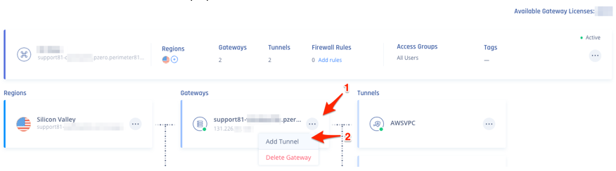
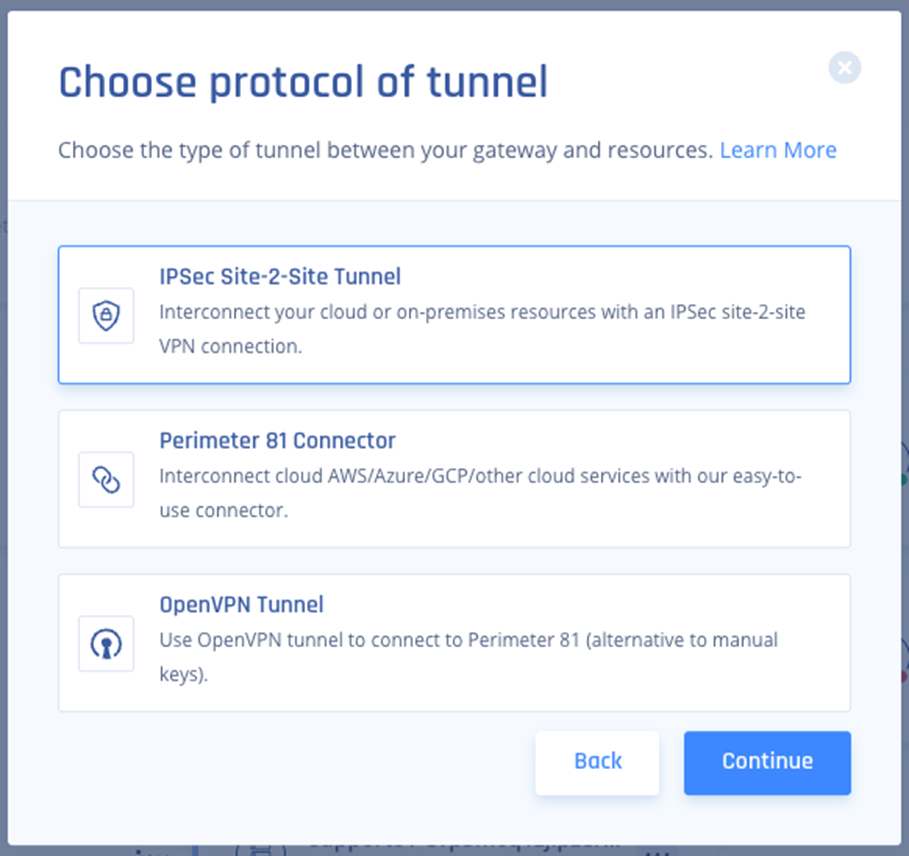
- Select IPSec Site-2-Site Tunnel and click Continue.
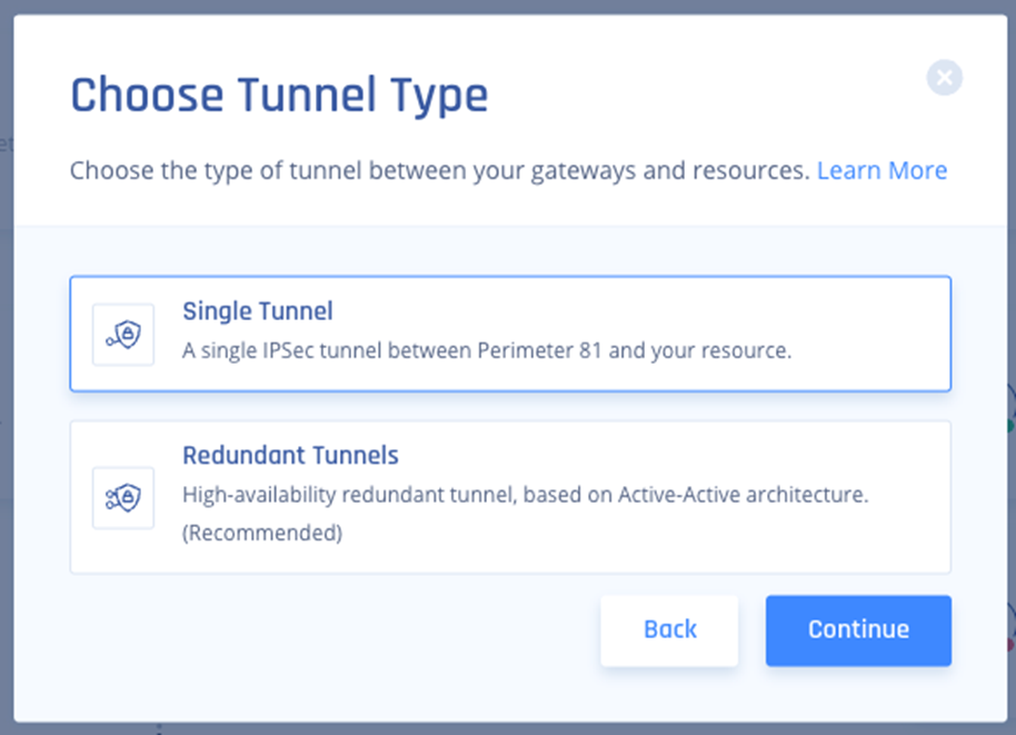
- Select Single Tunnel and click Continue.
- In the General Settings section, enter these:
- Name: Enter a name for the tunnel.
- Shared Secret: Enter a string or click Generate.
- Public IP: Enter the public IP of the Firepower device.
- Remote ID: Enter the remote ID of the Firepower device (this is same as Public IP unless the device is behind a NAT, then use the IP of the "outside" interface on the Firepower.)
- Check Point SASE Gateway Proposal Subnets: Leave Any (0.0.0.0/0) selected.
- Remote Gateway Proposal Subnets: Leave Any (0.0.0.0/0) selected.
.PNG)
- In the Advanced Settings section, specify these:
- IKE Version: V2
- IKE Lifetime: 8h
- Tunnel Lifetime: 1h
- Dead Peer Detection Delay: 10s
- Dead Peer Detection Timeout: 30s
- Phase 1:
- Encryption (Phase 1): aes256
- Integrity (Phase 1): sha256
- Key Exchange Method: modp2048
- Phase 2:
- Encryption (Phase 2): aes256
- Integrity (Phase 2): sha256
- Key Exchange Method: modp2048
.PNG)
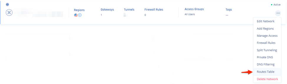
- On your network, click and select Routes Table.
- Click Add Route.
The Add Route window appears.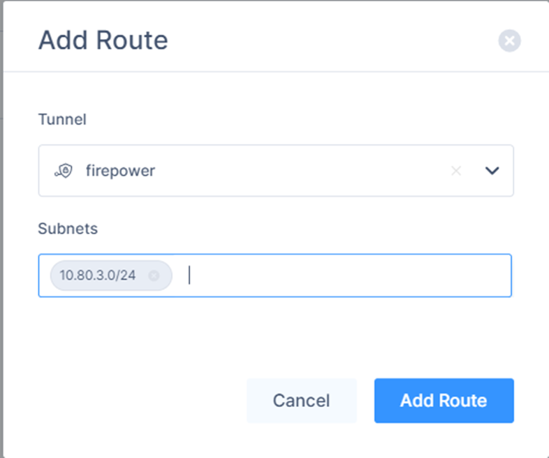
- Verify the field values.
- Click Add Route.
- Click Apply Configuration.

Configuring the Tunnel in Cisco Firepower
- Login to your Cisco Firepower web console.
- Select your device.

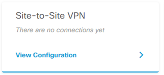
- Find your Site-to-Site VPN configuration and click View Configuration.
- Click
 to create a Site-to-Site Connection.
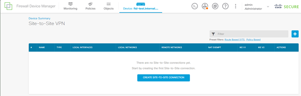
- Specify these:
- In the Connection Profile Name field, enter a name for your connection.
- In the Type section, select Route Based (VTI).
- Expand Local VPN Access Interface, and click Create new Virtual Tunnel Interface.
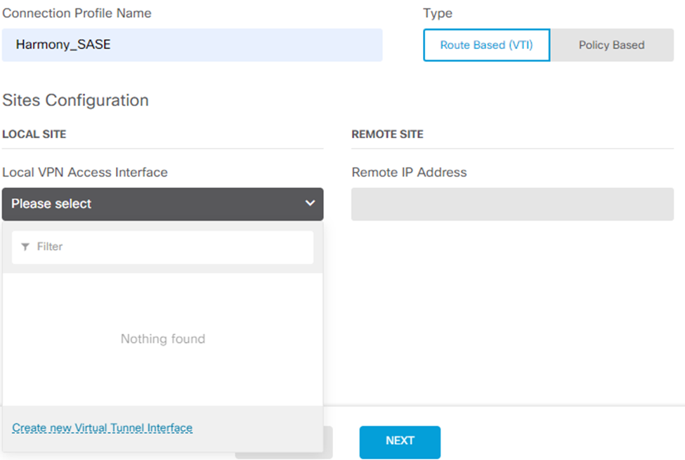 The Create Virtual Tunnel Interface window appears.
- Enter a name for your VTI adapter, for example, harmony_sase_vti.
- Turn on the Status toggle button.
- Enter a Tunnel ID.
- Set the source to your outside interface.
- Set the IP and Subnet Mask to 169.254.2.122 / 255.255.255.252
- Click OK.
- From the Create Virtual Tunnel Interface list, select the newly created VTI object.
- In the Remote IP Address field, enter your Check Point SASE gateway IP address (found in your Check Point SASE Admin Panel).
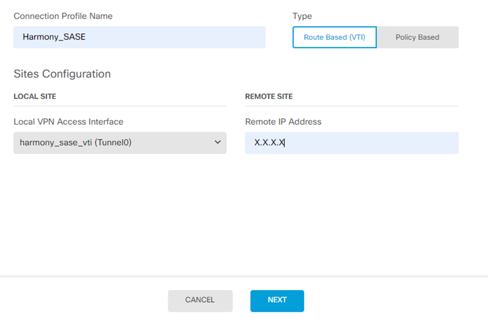
- Click Next.
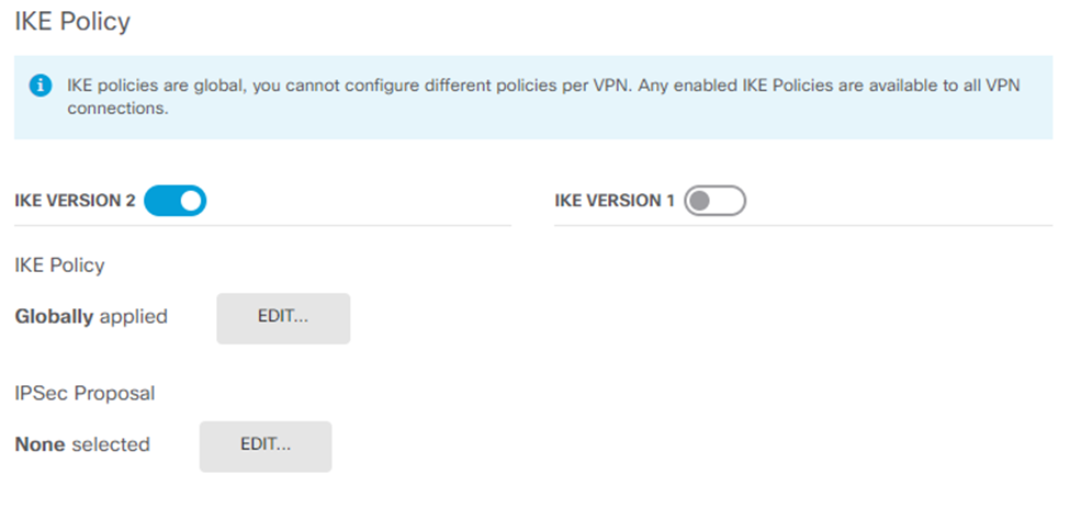
- Make sure the IKE VERSION 2 is enabled.
- In the IKE Policy section, for Globally applied, click Edit.
- Create a new policy with the settings that match the Phase 1 settings on the Check Point SASE side. Specify these:
- Priority
- Name
- State - Enable
- Encryption: AES256
- Diffie-Hellman Group: 14
- Integrity Hash: SHA256
- Pseudo Random Function (PRF) Hash: SHA256
- Lifetime: 28800
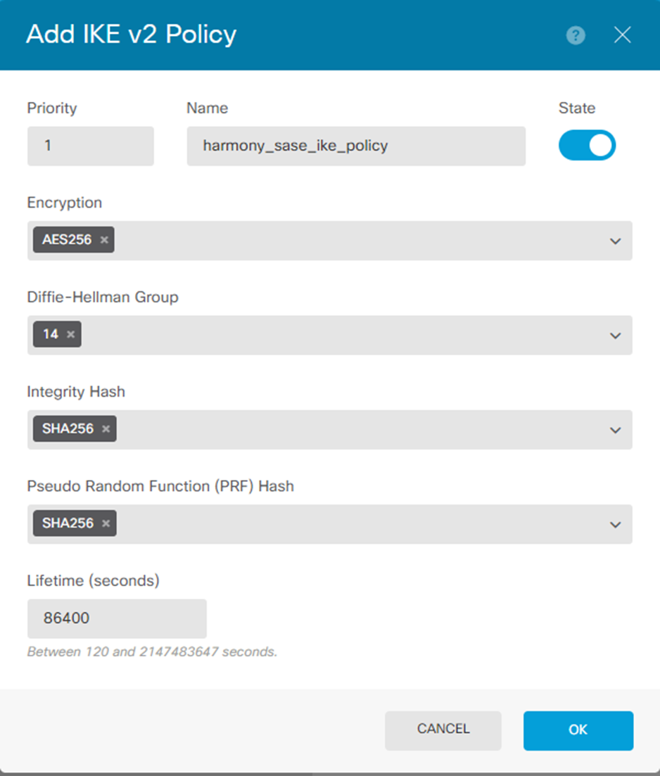
- Click OK.
- Click Edit by IPSec Proposal.
- Click Create new IPSec Proposal.
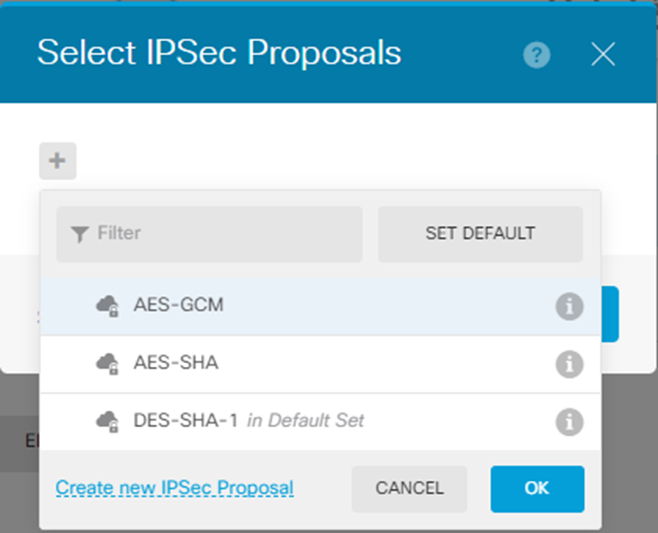
- Specify these:
- Name
- Encryption: AES256
- Integrity Hash: SHA256Note:Select the Encryption and Integrity Hash to match the Check Point SASE side for Phase 2.
- Click OK.
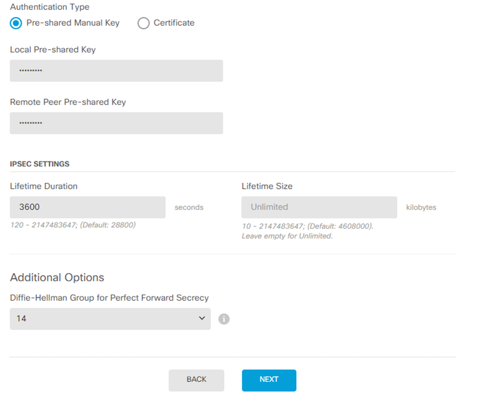
- In the Authentication Type section, select Pre-shared Manual Key.
- In the Local Pre-shared Key and Remote Peer Pre-shared Key fields, enter the Pre-shared Key that you created on the Check Point SASE portal.
- In the Lifetime Duration field, enter 3600.
- In the Diffie-Hellman Group for Perfect Forward Secrecy field, enter 14.
- Click Next.
- Click Finish.
- Click
 to deploy changes to apply the new tunnel.
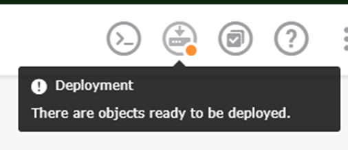
Configuring the Static Route in the Cisco Firepower
- Select your device.

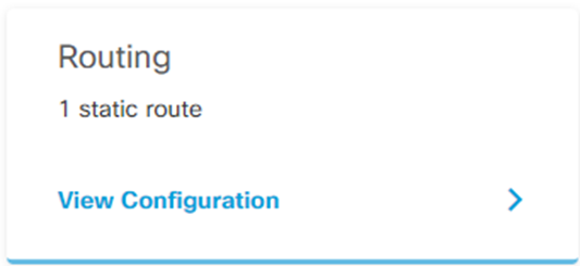
- In the Routing section, click View Configuration.
- Click to add a new static route.
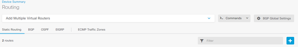 The Add Static Route window appears.
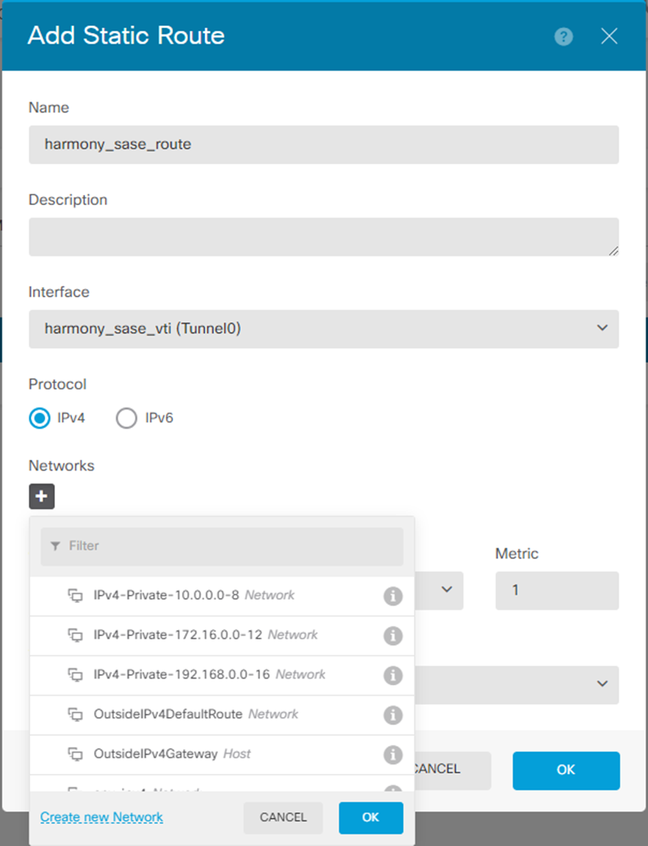
- In the Name field, enter a name for your static route.
- In the Description field, enter a description.
- From the Interface list, select the interface you created in Configuring the Tunnel in the Cisco Firepower step 6.
- In the Networks section, click
 .
. - Click Create new Network.
The Add Network Object window appears.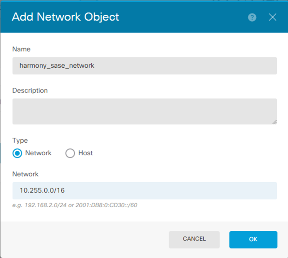
- Specify these:
- Name
- Description
- Type - Network
- Network - 10.255.0.0/16 (default)
- Click OK.
- In the Networks section, click .
- Select the object you just created.
- In the Gateway section, click Create new Network Object.
The Add Network Object window appears.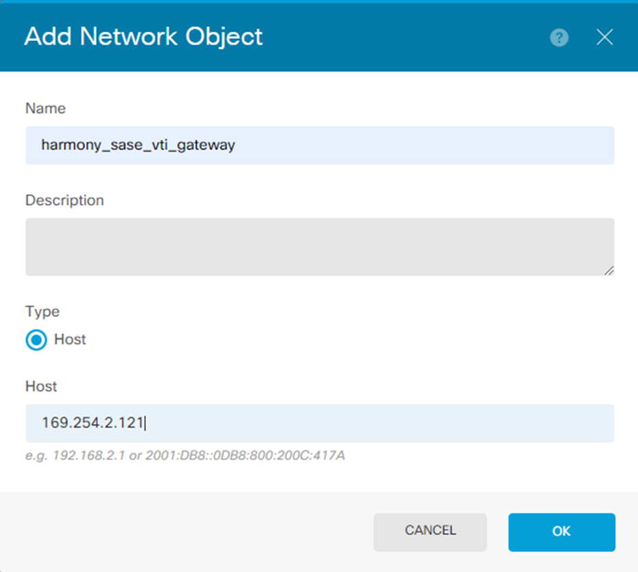
- Specify these:
- Name. For example, harmony_sase_vti_gateway
- Description
- Type - Host
- Network - 169.254.2.121 (this is the corresponding side of your VTI adapter)
- Click OK.
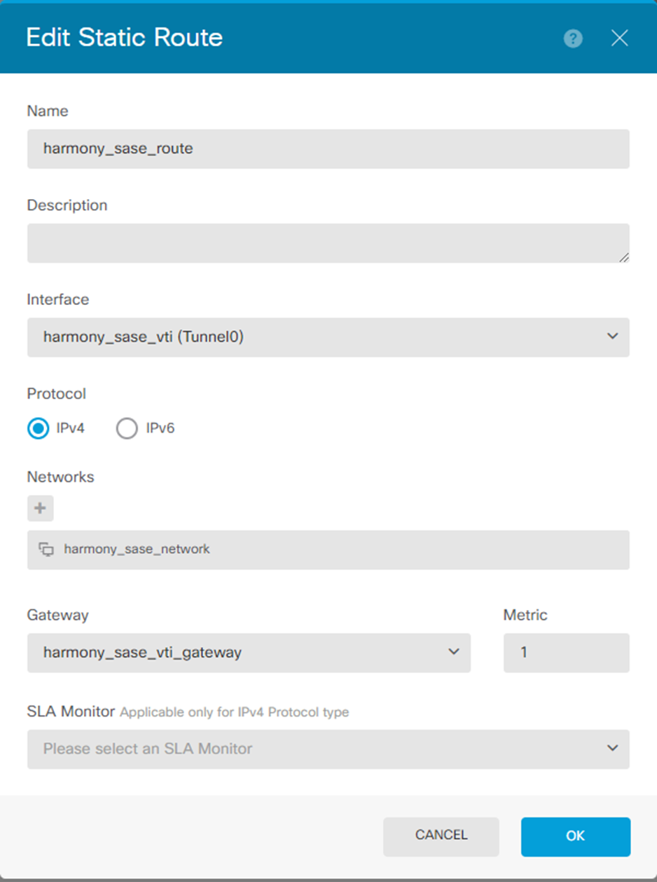 The new route is added.
- Click to deploy changes to apply the new route.

Configuring Firepower Policies Allowing Traffic Flow
To configure Cisco Firepower policies to allow traffic to flow:
- Go to Policies and click
 to add a new access rule.
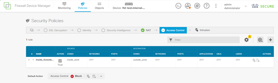
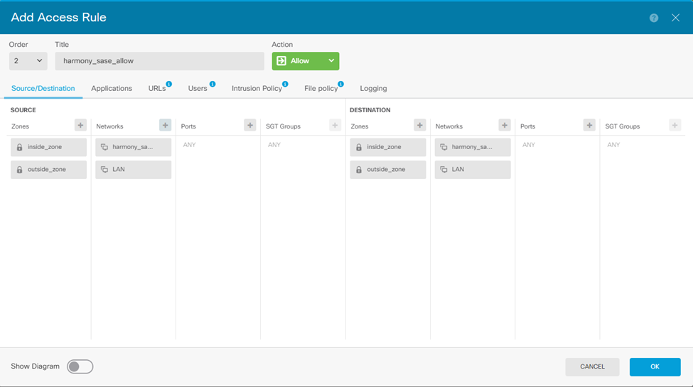
- Configure either 1 bidirectional rule or 2 unidirectional rules.
For example: Creating a single bidirectional rule.- Enter an order number. Make sure this rule is not after a block rule that affects this traffic.
- Enter a title. For example, harmony_sase_allow.
- Set your Source zones and Networks.
- Add an entry for inside_zone and outside_zone.
- Add a network entry for your harmony_sase_network object.
- Repeat the same for the Destination.
- Click OK.
Once you add the rule, the table should display: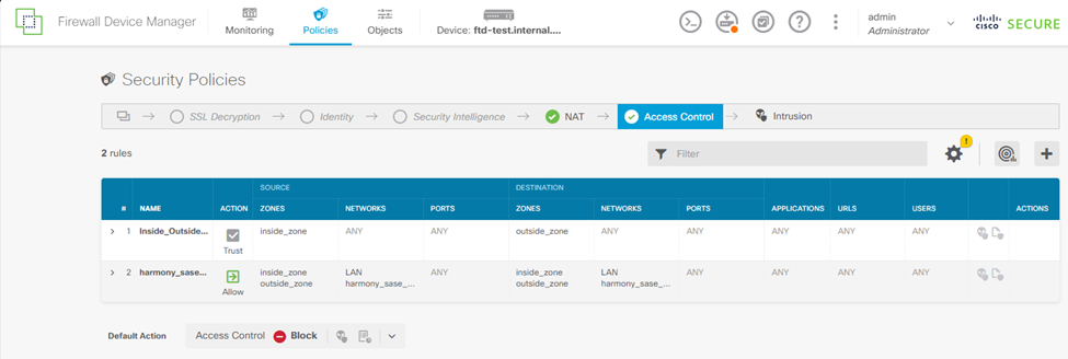
- Click to deploy changes to apply the new route.